Modeling simplifies database design and maintenance by enabling you, the data architect, to visualize requirements and resolve design issues. Model-driven database design is an efficient methodology for creating valid and well-performing databases, while providing the flexibility to respond to evolving data requirements. Models are used to build ER diagrams and physical MySQL databases.
MySQL Workbench provides extensive capabilities for creating and manipulating database models, including these:
Create and manipulate a model graphically
Reverse engineer a live database to a model
Forward engineer a model to a script or live database
Create and edit tables and insert data
This is not an exhaustive list. The following sections discuss these and additional data-modeling capabilities.
TODO: This information is from the previous manual, so requires reorganization
9.1.1 Model Editor
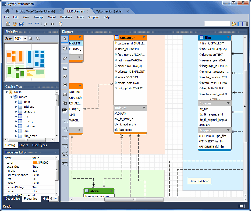
When the Model Editor is executed from the Home window, MySQL Workbench displays the MySQL Model page. The MySQL Model page has three main panels, as shown in the following screenshot: Description Editor, User Types List/History panel, and Model Overview.
Figure 9.1 The MySQL Model Page
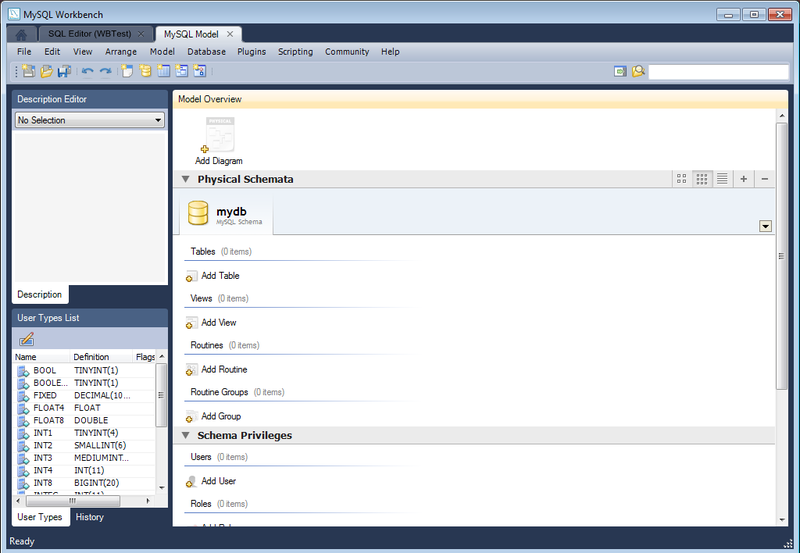
The Description Editor and User Types List/History panel are contained within the Sidebar. The Sidebar is located on the left by default, but can be relocated to the right using a setting in the Workbench Preferences dialog.
The Model Overview panel includes the following sections:
EER Diagrams
Physical Schemata
Schema Privileges
SQL Scripts
Model Notes
For each of these sections, add objects to a project by clicking the appropriate add-object icon. You may also rename, edit, cut, copy, or delete objects on this page by right-clicking to open a pop-up menu.
The following sections further discuss the MySQL Model page.
9.1.1.1 Modeling Menus
Some menu items are not available in the MySQL Workbench Community edition of this application, and are available only in MySQL Workbench Commercial. This is indicated where applicable.
9.1.1.1.1 The File Menu
Use the File menu to open a project, begin a new project, or save a project. Choosing Model opens the default schema, mydb. Choosing Open Model opens a file dialog box with the default file type set to MySQL Workbench Models (mwb extension). To display a list of recently opened MWB files, choose the Open Recent menu item. The keyboard shortcut to create a new project is Control+N and the command to open an existing project is Control+O.
To close the currently active MySQL Model or EER Diagram tab, use the Close Tab menu item. You can also do this from the keyboard by pressing Control+W. To reopen the MySQL Model tab, see Section 9.1.1.1.3, “The View Menu”. To reopen an EER Diagram tab, double-click the EER Diagram icon in the EER Diagrams section of the MySQL Model page.
Use the Save Model or Save Model As menu items to save a model. When you save a model, its name appears in the title bar of the application. If you have made changes to a project and have not saved those changes, an asterisk appears in the title bar following the model name. When you save a model, it is saved as a MySQL Workbench file with the extension mwb.
Use the Import menu item to import a MySQL data definition (DDL) script file. For example, this might be a file created by issuing the command mysqldump --no-data. MySQL Workbench handles the script as follows:
If the script does not contain a
CREATE DATABASE db_name; statement, the schema objects are copied to the default schema,mydb.If the script creates a database, a new tab bearing the database name is added to the
Physical Schematasection of theMySQL Modelpage.If the script contains data, the data is ignored.
For details about importing a DDL script, see Section 9.4.2.1, “Reverse Engineering Using a Create Script”.
Under the Import submenu, you can also import DBDesigner4 files.
There are variety of items under the Export submenu. You may generate the SQL statements necessary to create a new database or alter an existing one. For more information about these menu items, see Section 9.4.1.1, “Forward Engineering Using an SQL Script”.
Using the Export submenu, you can also export an EER diagram as a PNG, SVG, PDF, or Postscript file. For an example of a PNG file, see Figure 9.29, “The sakila Database EER Diagram”.
The Page Setup menu item enables you to set the paper size, orientation, and margins for printing purposes.
The printing options are enabled only if the EER Diagrams tab is selected. You have the choice of printing your model directly to your printer, printing it as a PDF file, or creating a PostScript file. For more information, see Section 9.2.1, “Printing Diagrams”.
Note
The printing options are available only in commercial versions of MySQL Workbench.
Use the Document Properties menu item to set the following properties of your project:
Name: The model name (default isMySQL Model)Version: The project version numberAuthor: The project authorProject: The project nameCreated: Not editable; determined by the MWB file attributesLast Changed: Not editable; determined by the MWB file attributesDescription: A description of your project
9.1.1.1.2 The Edit Menu
Use the Edit menu to make changes to objects. The menu item text descriptions change to reflect the name of the selected object.
This menu has items for cutting, copying, and pasting. These actions can also be performed using the Control+X, Control+C, and Control+V key combinations. Undo a deletion using the Undo Delete ‘object_name’ item. The Control+Z key combination can also be used to undo an operation. It is also possible to carry out a Redo operation using either the menu item, or the key combination Control+Y.
Also find a Delete ‘object_name’ menu item for removing the currently selected object. The keyboard command for this action is Control+Delete. You can also right-click an object and choose the delete option from the pop-up menu.
The Delete ‘object_name’ menu item behaves differently depending upon circumstances. For example, if an EER Diagram is active and a table on the canvas is the currently selected object, a dialog box may open asking whether you want to remove the table from the canvas only or from the database as well. For information about setting the default behavior when deleting from an EER Diagram, see Section 3.2.4, “Modeling Preferences”.
Warning
If the MySQL Model page is active, the selected object is deleted from the catalog and there will be no confirmation dialog box.
Choose Edit Selected to edit the currently selected object. You can also perform edits in a new window by selecting Edit Selected in New Window. The keyboard shortcuts for Edit Selected and Edit Selected in New Window are Control+E and Control+Shift+E, respectively.
The Select item has the following submenus:
Select All (Keyboard shortcut, Control+A): Selects all the objects on the active EER diagram.
Similar Figures (Objects of the same type): Finds objects similar to the currently selected object.
Connected Figures: Finds all the objects connected to the currently selected object.
These menu items are active only when an EER Diagram tab is selected. The Similar Figures and the Connected Figures menu items are disabled if no object is currently selected on an EER diagram.
When multiple objects have been selected using one of these menu items, you can navigate between selected items by choosing the Go to Next Selected or Go to previous Selected menu item.
Selecting objects changes some of the Edit menu items. If only one object is selected, that object’s name appears after the Cut, Copy and Delete menu items. If more than one object is selected, these menu items show the number of objects selected.
9.1.1.1.2.1 Find Dialog Window
Each MySQL Workbench window includes search functionality. The Find panel with Find & Replace enabled is shown below:
Figure 9.2 The Find Panel with Find & Replace
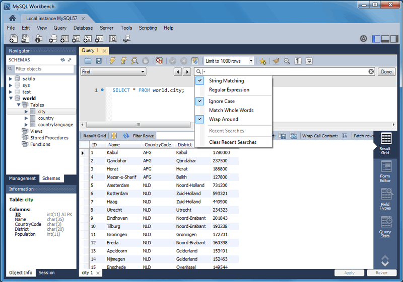
Find options The Find dialogue options are described below:
String Matching (default) or Regular Expression: Search by matching a string, or a PCRE regular expression.
Ignore Case: A case-insensitive search. Works with both the String Matching and Regular Expression search methods. Enabled by default.
Match Whole Words: If enabled, only whole strings are matched. For example, a search for “home” would not match “home_id”. Disabled by default.
Wrap Around: The search will wrap around to the beginning of the document, as otherwise it will only search from the cursor position to the end of the document. Enabled by default.
And the arrows jump to the discovered search terms, and behave according to the Wrap Around option.
The MySQL Workbench Commercial edition includes an advanced Find facility for models:
Figure 9.3 The Find Window
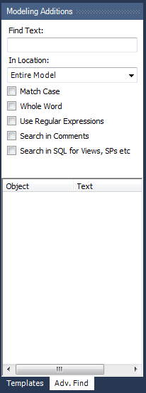
You can search the following locations:
Entire Model: Searches the entire model.
Current View: Searches the current view only. This may be the
MySQL Modelpage.All Views: Searches the
MySQL Model Pageand all EER diagrams.Database Objects: Searches database objects only.
Selected Figures: Searches the currently selected objects. This feature works only for EER diagrams.
Enter the text you wish to search for in the Find Text list. You may also select any or all of the following check boxes:
Match Case
Whole Word
Use Regular Expression
Search in Comments
Search in SQL for Views, SPs etc.
Any text you enter into the Find Text list is retained for the duration of your session. Use the Next or Previous buttons to find occurrences of your search criterion.
Clicking the Find All button opens a Find Results window anchored at the bottom of the application. If you wish, you may undock this window as you would any other.
Use this window to navigate to objects. For example, double-clicking the Description of an object located on an EER diagram navigates to the specific diagram and selects the object. Notice that the properties of the object are displayed in the Properties palette.
The Find dialog window can also be opened using the Control+F key combination. Use Control+G to find the next occurrence and Control+Shift+G to find a previous occurrence. Close the Find dialog window by clicking the x in the top right corner or by pressing the Esc key.
9.1.1.1.2.2 Workbench Preferences
This menu item enables you to set global preferences for the MySQL Workbench application.
For further information, see Section 3.2, “Workbench Preferences”.
9.1.1.1.3 The View Menu
This context-aware menu features general options for changing the view in MySQL Workbench. These options change depending on the current tab, and here are the available View menu items:
General options:
Home: Selects the Home window
Panels: Configure which of the three available panels are open. You may also manage this from the GUI using the panel toggle buttons on the top-right side of MySQL Workbench.
Output: Displays the console output.
Select Next Main Tab: Selects the next (moves to the right, and wraps around) MySQL Workbench tab.
Select Next Main Tab: Selects the previous (moves to the left, and wraps around) MySQL Workbench tab.
Model/EER options:
Windows: A submenu with items that activate (slide open) specific panels. Designated panels include the “Model Navigator”, “Catalog”, “Layers”, “User Datatypes”, “Object Descriptions”, “Object Properties”, and “Undo History”.
Zoom 100%: The default level of detail of an EER diagram
Zoom In: Zooms in on an EER diagram.
Zoom Out: Zooms out from an EER diagram.
The ability to zoom in on an EER diagram is also available using the slider tool in the
Model Navigatorpalette. See Section 9.1.1.9, “The Model Navigator Panel”.Set Marker: Bookmarks an object. From the keyboard, select the object you wish to bookmark, then use the key combination Control+Shift and the number of the marker (1 through 9). You may create up to nine markers.
Go To Marker: Returns to a marker. From the keyboard, use the Control key and the number of the marker.
Toggle Grid: Displays grid lines on an EER diagram.
Toggle Page Guides: Toggles Page Guides to help design the EER diagram on a per-page basis.
9.1.1.1.4 The Arrange Menu
The Arrange menu items apply only to objects on an EER diagram canvas and are enabled only if an EER diagram view is active. The Arrange menu has these items:
Align to Grid: Aligns items on the canvas to the grid lines
Bring to Front: Brings objects to the foreground
Send to Back: Sends objects to the background
Center Diagram Contents: Centers objects on the canvas
Autolayout: Automatically arranges objects on the canvas
Reset Object Size: Expands an object on an EER diagram. For example, if a table has a long column name that is not fully displayed, this menu item expands the table to make the column visible. This menu item is not enabled unless an object is selected.
Expand All: Use this item to expand all objects on an EER diagram. This item will display a table’s columns if the object notation supports expansion. Some object notations, such as
Classic, do not permit expansion or contraction. Indexes will not automatically be expanded unless they were previously expanded and have been collapsed using the Collapse All menu item.Collapse All: Undo the operation performed by Expand All.
9.1.1.1.5 The Model Menu
When a model is opened, this menu features actions to perform against your model, and the Model menu has these items:
Add Diagram: Creates a new EER Diagram. The keyboard shortcut is Control+T.
Create Diagram From Catalog Objects: Creates an EER diagram from all the objects in the catalog.
User Defined Types: Presents a dialog box that enables you to add and delete user defined data types.
DBDoc – Model Reporting…: For information about this menu item, see Section 9.1.1.1.5.1, “The DBDoc Model Reporting Dialog Window (Commercial Version)”. Commercial version only.
Validation: Checks the validity of the model using ANSI standards. For information about this menu item, see Section 9.1.1.1.5.2, “The Validation Submenus (Commercial Version)”. Commercial version only.
Validation (MySQL): Checks the validity of the model using MySQL standards. For information about this menu item, see Section 9.1.1.1.5.2, “The Validation Submenus (Commercial Version)”. Commercial version only.
Object Notation: For information about this menu item, see Section 9.1.1.1.5.3, “The Object Notation Submenu”.
Relationship Notation: For information about this menu item, see Section 9.1.1.1.5.4, “The Relationship Notation Submenu”.
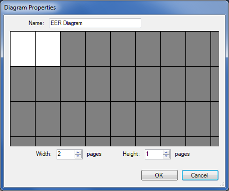
Diagram Properties and Size: Opens a diagram size dialog box that enables you to adjust the width or height of the canvas. The unit of measure is pages; the default value is two.
When you have tables with numerous columns, use this menu item to increase the size of the EER.
Model Options: Sets options at the model level. These options should not be confused with the options that are set globally for the Workbench application, and which are referred to as Workbench Preferences. The available model options are a subset of the Workbench Preferences options.
For more information about Workbench Preferences, see Section 3.2.4, “Modeling Preferences”.
9.1.1.1.5.1 The DBDoc Model Reporting Dialog Window (Commercial Version)
This dialog window is found by navigating to the Model menu and choosing the DBDoc - Model Reporting… item.
Note
The DBDoc - Model Reporting… item is not available in the MySQL Workbench Community version.
Use this dialog window to set the options for creating documentation of your database models. For more information, see Section 9.2.2, “DBDoc Model Reporting”.
9.1.1.1.5.2 The Validation Submenus (Commercial Version)
The Model menu has two validation submenus, Validation and Validation (MySQL). Use these submenus for general validation and MySQL-specific validation of the objects and relationships defined in your model.
Note
These items are not available in the MySQL Workbench Community version.
The Validation submenu has these items:
Validate All: Performs all available validation checks
Empty Content Validation: Checks for objects with no content, such as a table with no columns
Table Efficiency Validation: Checks the efficiency of tables, such as a table with no primary key defined
Duplicate Identifiers Validation: Checks for duplicate identifiers, such as two tables with the same name
Consistency Validation: Checks for consistent naming conventions
Logic Validation: Checks, for example, that a foreign key does not reference a nonprimary key column in the source table
The Validation (MySQL) submenu has these items:
Validate All: Performs all available validation checks
Integrity Validation: Checks for invalid references, such as a table name longer than the maximum permitted
Syntax validation: Checks for correct SQL syntax
Duplicate Identifiers Validation (Additions): Checks for objects with the same name
For detailed information about validation, see Section 9.2.3, “Schema Validation Plugins”.
9.1.1.1.5.3 The Object Notation Submenu
The items under the Model, Object Notation submenu apply exclusively to an EER diagram. They are not enabled unless an EER diagram tab is selected.
The Object Notation submenu has these items:
Workbench (Default): Displays table columns, indexes, and triggers
Workbench (Simplified): Shows only a table’s columns
Classic: Similar to the
Workbench (Simplified)style showing only the table’s columnsIDEF1X: The ICAM DEFinition language information modeling style
The object notation style that you choose persists for the duration of your MySQL Workbench session and is saved along with your model. When MySQL Workbench is restarted, the object notation reverts to the default.
Note
If you plan to export or print an EER diagram be sure to decide on a notation style first. Changing notation styles after objects have been placed on a diagram can significantly change the appearance of the diagram.
9.1.1.1.5.4 The Relationship Notation Submenu
The items under the Relationship Notation submenu apply exclusively to an EER diagram. They are not enabled unless an EER diagram tab is selected.
The Relationship Notation submenu has these items:
Crow’s Foot (IE): The default modeling style. For an example, see Figure 9.24, “Adding Tables to the Canvas”.
Classic: Uses a diamond shape to indicate cardinality.
Connect to Columns
UML: Universal Modeling Language style.
IDEF1X: The ICAM DEFinition language information modeling method
To view the different styles, set up a relationship between two or more tables and choose the different menu items.
The relationship notation style that you choose persists for the duration of your MySQL Workbench session and is saved along with your model. When MySQL Workbench is restarted, the relationship notation reverts to the default, the Crow's Foot style.
Note
If you plan to export or print an EER diagram, be sure to decide on a notation style first. Changing notation styles after objects have been placed on a diagram can significantly change the appearance of the diagram.
9.1.1.1.6 The Database Menu
This menu features actions against the connected MySQL server. The Database menu has these items:
Query Database: Launches the SQL Editor, which enables you to create SQL code and execute it on a live server. For more information, see Section 8.1, “Visual SQL Editor”.
Manage Connections: Launches the Manage Server Connections dialog, which enables you to create and manage multiple connections. For more information, see Section 5.3, “Manage Server Connections”
Reverse Engineer: Creates a model from an existing database. For more information, see Section 9.4.2.2, “Reverse Engineering a Live Database”.
Forward Engineer: Creates a database from a model. For more information, see Section 9.4.1.2, “Forward Engineering to a Live Server”.
Schema Transfer Wizard…: Executes the database migration wizard for MySQL databases. It is useful for moving from an older MySQL server to the latest MySQL version, and is meant for local development purposes. You should not use this tool on production MySQL instances as they often require more complex data migration techniques.
For additional information about this wizard, see MySQL Schema Transfer Wizard.
Migration Wizard…: Executes the database migration wizard for most any database, and is meant to migrate tables and data from supported database systems to your MySQL server. For additional information, see Chapter 10, Database Migration Wizard.
Edit Type Mappings for Generic Migration: From here you can define custom type mappings, such as migrating the source data type
int8to the target MySQL data typeBIGINT.Synchronize Model: Synchronizes your database model with an existing database. For more information, see Section 9.5.1, “Database Synchronization”.
Synchronize with Any Source: Allows you to compare a target database or script with the open model, external script, or a second database, and apply these changes back to the target. For more information, see Section 9.5.1, “Database Synchronization”.
Compare Schemas: Compares your schema model with a live database or a script file. Section 9.5.2, “Compare and Report Differences in Catalogs”.
9.1.1.1.7 The Tools Menu
The Tools menu lists tools and utilities that related to MySQL Workbench usage.
Browse Audit Log File: Launches a file browser to open a specific audit log file. MySQL Workbench prompts for sudo access if the MySQL Workbench user is unable to read the audit log file. For additional information about the Audit Inspector, see Section 6.6, “MySQL Audit Inspector Interface”. Commercial only.
Configuration: Backup (or restore) your MySQL Connections, as defined in MySQL Workbench. Connection data is stored in a
connections.xmlfile, for additional information about this file, see Section 3.3, “MySQL Workbench Settings and Log Files”.Utilities: These utilities generate PHP code to either “Connect to the MySQL server” or “Iterate SELECT results”, if applicable. For additional information about PHP code generation, see Section 8.1.12.2, “Generating PHP Code”.
Start Shell for MySQL Utilities: Opens the mysqluc MySQL Utility. For additional information about MySQL Utilities, see Appendix F, MySQL Utilities.
9.1.1.1.8 The Scripting Menu
This menu features GRT scripting and plugin options. The Scripting menu has these items:
Scripting Shell: Launches the MySQL Workbench Scripting Shell. For additional information, see Section C.5, “The Workbench Scripting Shell”.
New Script: Opens a New Script File dialogue, with options to create a Python Script, Python Plugin, or Python Module.
Open Script: Opens a Open GRT Script dialogue, which defaults to the Workbench scripts directory. Files are opened into the Workbench Scripting Shell window.
Run Script File: Executes the script that is currently open.
Run Workbench Script File: Executes the specified script file.
Install Plugin/Module File: Loads and installs a plugin or module file
Plugin Manager: Displays information about the plugins that are installed, and allows disabling and uninstalling the plugins.
9.1.1.1.9 The Help Menu
Use the Help menu when you require support, or when you want to help improve MySQL Workbench. This menu has the following items:
Help Index: Opens a window showing a local copy of the MySQL Workbench documentation. Read, search, or print the documentation from this window.
MySQL.com Website: Opens your default browser on the MySQL Web site home page.
Workbench Product Page: Opens your default browser on the MySQL Workbench product page.
System Info: Displays information about your system, which is useful when reporting a bug. For more information, see Section 9.1.1.1.9.1, “System Info”.
Report a Bug: Opens your default browser to bugs.mysql.com, and automatically fills in several fields such as the Operating System and MySQL Workbench version by passing in additional data via the GET request. The default “Description” requests you to also attach the Workbench log file. For additional information about reporting useful bug reports, see Appendix D, How To Report Bugs or Problems.
View Reported Bugs: Opens your default browser to see a list of current bugs.
Locate Log Files: Opens up the directory that contains the MySQL Workbench log files.
Show Log File: Opens up the main MySQL Workbench log file in your default text editor. This file is typically named
wb.log.Check For Updates: Checks if you are using the current MySQL Workbench version. If you are, then a popup informs you of this. If not, then a prompt asks you to open the MySQL Workbench download page.
About Workbench: Displays the MySQL Workbench
Aboutwindow. This also displays the MySQL Workbench version.
9.1.1.1.9.1 System Info
Use the Help, System Info menu item to display information about your system. This item is especially useful for determining your rendering mode. Sample output follows.
MySQL Workbench Community (GPL) for Windows version 6.1.4  revision 11773 build 1454
Configuration Directory: C:\Users\philip\AppData\Roaming\MySQL\Workbench
Data Directory: C:\Users\philip\Desktop\MySQL\MySQL Workbench 6.1.4 CE
Cairo Version: 1.8.8
OS: Microsoft Windows 7  Service Pack 1 (build 7601), 64-bit
CPU: 4x Intel(R) Core(TM) i5-2400 CPU @ 3.10GHz, 8.0 GiB RAM
Active video adapter NVIDIA GeForce GT 610
Installed video RAM: 1024 MB
Current video mode: 1920 x 1080 x 4294967296 colors
Used bit depth: 32
Driver version: 9.18.13.2049
Installed display drivers: nvd3dumx.dll,nvwgf2umx.dll,nvwgf2umx.dll,nvd3dum,nvwgf2um,nvwgf2um
Current user language: English (United States)
9.1.1.2 The Toolbar
The MySQL Workbench toolbar is located immediately below the menu bar. Click the tools in the toolbar to perform the following actions:
The new document icon: Creates a new document
The folder icon: Opens a MySQL Workbench file (
mwbextension)The save icon: Saves the current MySQL Workbench project
The right and left arrows: The left arrow performs an “Undo” operation. The right arrow performs a “Redo” operation.
Other tools appear on the toolbar depending upon the context.
9.1.1.2.1 Tool-Specific Toolbar Items
When an EER diagram canvas is selected, the following icons appear to the right of the arrow icons:
The toggle grid icon: Turns the grid on and off
The grid icon: Aligns objects on the canvas with the grid
The new EER diagram icon: Creates a new EER diagram tab.
The toolbar also changes depending upon which tool from the vertical toolbar is active. For discussion of these tools, see Section 9.1.2.1, “The Vertical Toolbar”.
If the Table tool is active, schemata lists, engine types, and collations appear on the toolbar. The table properties can be modified using the Properties Editor.
When an object is selected, the object’s properties, such as color, can be changed in the Properties Editor.
9.1.1.3 EER Diagrams
Use the Add new Diagram icon in the MySQL Model area to create EER diagrams. When you add an EER diagram, a new tab appears below the toolbar. Use this tab to navigate to the newly created EER diagram. For further discussion of EER Diagrams, see Section 9.1.2, “EER Diagram Editor”.
9.1.1.4 The Physical Schemata Panel
The Physical Schemata panel of the MySQL Model page shows the active schemata and the objects that they contain.
Expand and contract the Physical Schemata section by double-clicking the arrow on the left of the Physical Schemata title bar. When the Physical Schemata section is expanded, it displays all currently loaded schemata.
Each schema shows as a tab. To select a specific schema, click its tab. When MySQL Workbench is first opened, a default schema, mydb, is selected. You can start working with this schema or you can load a new MySQL Workbench Model file (models use the .mwb extension.)
There are a variety of ways to add schema to the Physical Schemata panel. You can open an MWB file, reverse engineer a MySQL create script, or, if you are using a commercial version of MySQL Workbench, you can reverse engineer a database by connecting to a MySQL server.
You can also add a new schema by clicking the + button on the top right of the Physical Schemata panel. To remove a schema, click its tab and use the - button found to the immediate left of the + button. To the left of these buttons are three buttons that control how database object icons are displayed:
The left button displays database objects as large icons.
The middle button displays small icons in multiple rows.
The right button displays small icons in a single list.
9.1.1.4.1 The Schema Objects Panel
The Physical Schemata panel has the following sections:
Tables
Views
Routines
Routine Groups
Each section contains the specified database objects and an icon used for creating additional objects.
Any database objects added to an EER diagram canvas also show up in the Physical Schemata section. For information about adding objects to an EER diagram canvas, see Section 9.1.2, “EER Diagram Editor”.
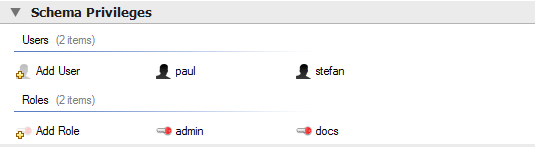
9.1.1.5 The Schema Privileges Panel
The Schema Privileges panel has the following sections, used to create users for your schemata and to define roles —:
Users
Roles
The following image displays the Schema Privileges section of the MySQL Model tab.
Figure 9.4 Roles and Privileges
9.1.1.5.1 Adding Roles
To add a role, double-click the Add Role icon. This creates a role with the default name role1. Right-clicking a role opens a pop-up menu with the following items:
Cut ‘
role_name’: Cuts the roleCopy ‘
role_name’: Copies the roleEdit Role…: Opens the role editor
Edit in New Window…: Opens the role editor in a new editor window
Delete ‘
role_name’: Removes the roleCopy SQL to Clipboard: Currently not implemented
To rename a role, click the role name. Then you will be able to edit the text.
All defined roles are listed under Roles on the left side of the role editor. Double-clicking a role object opens the role editor docked at the bottom of the page.
Figure 9.5 Role Editor
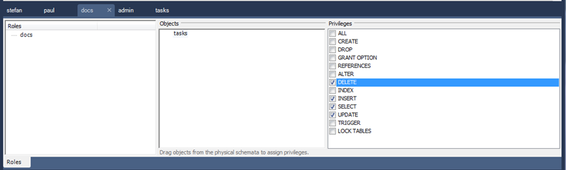
Select the role to which you wish to add objects. You may drag and drop objects from the Physical Schemata to the Objects section of the role editor. To assign privileges to a role, select it from the Roles section, then select an object in the Objects section. In the Privileges section, check the rights you wish to assign to this role. For example, a web_user role might have only SELECT privileges and only for database objects exposed through a web interface. Creating roles can make the process of assigning rights to new users much easier.
9.1.1.5.2 Adding Users
To add a user, double-click the Add User icon. This creates a user with the default name user1. Double-clicking this user opens the user editor docked at the bottom of the application.
In the User Editor, set the user’s name and password using the Name and Password fields. Assign one role or a number of roles to the user by selecting the desired roles from the field on the right and then clicking the < button. Roles may be revoked by moving them in the opposite direction.
Right-clicking a user opens a pop-up menu. The items in the menu function as described in Section 9.1.1.5.1, “Adding Roles”.
9.1.1.6 The SQL Scripts Panel
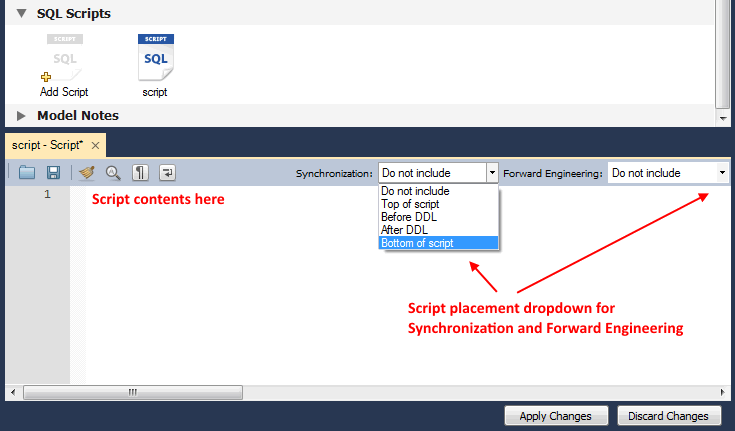
Use the SQL Scripts panel to attach SQL scripts to the model for documentation and organizational purposes, and optionally these attachments can be included in the output script when performing forward engineering or model/schema synchronization.
If you created your project from an SQL script and plan to create an ALTER script, you may want to add the original script here, since it will be needed to create an ALTER script. For more information, see Section 9.4.1.1.2, “Altering a Schema”.
Note
The ability to use the attachments when performing forward engineering and synchronization was added in MySQL Workbench 6.2.0.
Figure 9.6 SQL Scripts Editor
9.1.1.7 The Model Notes Panel
Use the Model Notes panel to write project notes. Any scripts or notes added will be saved with your project.
9.1.1.8 The History Palette
Use the History palette to review the actions that you have taken. Left-clicking an entry opens a pop-up menu with the item, Copy History Entries to Clipboard. Choose this item to select a single entry. You can select multiple contiguous entries by pressing the Shift key and clicking the entries you wish to copy. Select noncontiguous entries by using the Control key.
Only actions that alter the MySQL model or change an EER diagram are captured by the History palette.
9.1.1.9 The Model Navigator Panel
Docked at the top left of the application is the Model Navigator, or Bird’s Eye panel. This panel provides an overview of the objects placed on an EER diagram canvas and for this reason it is most useful when an EER diagram is active. Any objects that you have placed on the canvas should be visible in the navigator.
The Model Navigator shows the total area of an EER diagram. A black rectangular outline indicates the view port onto the visible area of the canvas. To change the view port of an EER diagram, left-click this black outline and drag it to the desired location. You can zoom in on selected areas of an EER diagram by using the slider tool at the bottom of this window. The dimensions of the view port change as you zoom in and out. If the slider tool has the focus, you can also zoom using the arrow keys.
Figure 9.7 The Model Navigator: Example
The default size of the Model Navigator is two pages. Use the Model, Diagram Properties and Size page to change the size and diagram name.
Figure 9.8 The Model Navigator Palette
9.1.1.10 The Catalog Tree Palette
The Catalog Tree palette shows all the schemata that are present in the Physical Schemata section of the MySQL Model page. Expand the view of the objects contained in a specific schema by clicking the > button to the left of the schema name. This displays the following folder icons:
Tables
Views
Routine Groups
Expand each of these in turn by clicking the > button to the left of the folder icon.
The Catalog Tree palette is primarily used to drag and drop objects onto an EER diagram canvas.
You can toggle the sidebar on and off using the Toggle Sidebar button, which is located in the top right of the application.
9.1.1.11 The Layers Palette
This palette shows all of the layers and figures on an EER diagram. If a layer or figure is currently selected, an X appears beside the name of the object and its properties are displayed in the Properties palette. This is useful when determining the selected objects multiple objects were selected using the options under the Select menu item. For more information on this topic, see Section 9.1.1.1.2, “The Edit Menu”.
Selecting an object in the Layers palette also adjusts the view port to the area of the canvas where the object is located.
9.1.1.11.1 Finding Invisible Objects Using the Layers Palette
In some circumstances, you may want to make an object on an EER diagram invisible. Select the object and, in the Properties palette, set the visible property to False.
The Layer palette provides an easy way to locate an object, such as a relationship, that has been set to hidden. Open the Layers palette and select the object by double-clicking it. You can then edit the object and change its visibility setting to Fully Visible.
9.1.1.12 The Properties Palette
The Properties palette is used to display and edit the properties of objects on an EER diagram. It is especially useful for editing display objects such as layers and notes.
Selecting an object in the EER diagram displays its properties in the Properties palette.
All objects except connections have the following properties except as noted:
color: The color accent of the object, displayed as a hexadecimal value. Change the color of the object by changing this value. Only characters that are legal for hexadecimal values may be entered. You can also change the color by clicking the … button to open a color changing dialog box.description: Applicable to layers only. A means of documenting the purpose of a layer.expanded: This attribute applies to objects such as tables that can be expanded to show columns, indexes, and triggers.height: The height of the object. Depending upon the object, this property may be read only or read/write.left: The number of pixels from the object to the left side of the canvas.locked: Whether the object is locked. The value for this attribute is eithertrueorfalse.manualSizing: Whether the object was manually sized. The value for this attribute is eithertrueorfalse.name: The name of the object.top: The number of pixels from the object to the top of the canvas.visible: Whether the object shows up on the canvas. Use‘1’for true and‘0’for false. It is currently used only for relationships.width: The width of the object. Depending upon the object, this property may be read only or read/write.
Tables have the following additional properties:
indexesExpanded: Whether indexes are displayed when a table is placed on the canvas. Use‘1’for true and‘0’for false.triggersExpanded: Whether triggers are displayed when a table is placed on the canvas. Use‘1’for true and‘0’for false.
For a discussion of connection properties, see Section 9.1.4.3, “Connection Properties”.
9.1.2 EER Diagram Editor
EER diagrams are created by double-clicking the Add Diagram icon. You may create any number of EER diagrams just as you may create any number of physical schemata (databases). Each EER diagram shows as a tab below the toolbar; a specific EER diagram is selected by clicking its tab.
Clicking an EER diagram tab navigates to the canvas used for graphically manipulating database objects. The Vertical Toolbar is on the left side of this page.
Note
This tool is for creating and editing EER diagrams for a model. To edit an existing database, either reverse engineer the database to create a model, or syncronize your model to a database. For additional information, see Section 9.4.2.2, “Reverse Engineering a Live Database” and Section 9.5, “Schema Synchronization and Comparison”.
9.1.2.1 The Vertical Toolbar
The vertical toolbar shows on the left sidebar when an EER diagram tab is selected. The tools on this toolbar assist in creating EER diagrams.
Figure 9.9 The Vertical Toolbar
Clicking a tool changes the mouse pointer to a pointer that resembles the tool icon, indicating which tool is active. These tools can also be activated from the keyboard by pressing the key associated with the tool. Hover the mouse pointer over a toolbar icon to display a description of the tool and its shortcut key.
A more detailed description of each of these tools follows.
9.1.2.1.1 The Standard Mouse Pointer
The standard mouse pointer, located at the top of the vertical toolbar, is the default mouse pointer for your operating system. Use this tool to revert to the standard mouse pointer after using other tools.
To revert to the default pointer from the keyboard, use the Esc key.
9.1.2.1.2 The Hand Tool
The hand tool is used to move the entire EER diagram. Left-click on this tool and then left-click anywhere on the EER diagram canvas. Moving the mouse while holding down the mouse button changes the view port of the canvas.
To determine your position on the canvas, look at the Model Navigator panel on the upper right. If the Model Navigator panel is not open, use View, Windows, Model Navigator to open it.
To activate the hand tool from the keyboard, use the H key.
You can also change the view port of an EER diagram using the Model Navigator panel. See Section 9.1.1.9, “The Model Navigator Panel”.
9.1.2.1.3 The Eraser Tool
Use the eraser tool to delete objects from the EER Diagram canvas. Change the mouse pointer to the eraser tool, then click the object you wish to delete. Depending upon your settings, the delete dialog box should open, asking you to confirm the type of deletion.
Note
The delete action of the eraser tool is controlled by the general option setting for deletion. Before using the eraser tool, be sure that you understand the available options described in Section 3.2.4, “Modeling Preferences”.
To activate the eraser tool from the keyboard, use the D key.
You can also delete an object by selecting it and pressing Control+Delete or by right-clicking it and choosing Delete from the pop up menu.
9.1.2.1.4 The Layer Tool
The layer tool is the rectangular icon with a capital L in the lower left corner. Use the layer tool to organize the objects on an EER Diagram canvas. It is useful for grouping similar objects. For example, you may use it to group all your views.
Click the layer tool and use it to draw a rectangle on the canvas. Change to the standard mouse pointer tool and pick up any objects you would like to place on the newly created layer.
To change the size of a layer, first select it by clicking it. When a layer is selected, small rectangles appear at each corner and in the middle of each side. Adjust the size by dragging any of these rectangles.
You can also make changes to a layer by selecting the layer and changing properties in the Properties panel. Using the Properties panel is the only way to change the name of a layer.
To activate the layer tool from the keyboard, use the L key. For more information about layers, see Section 9.1.7, “Creating Layers”.
9.1.2.1.5 The Text Tool
The text tool is the square icon with a capital N in the top left corner. Use this tool to place text objects on the EER diagram canvas. Click the tool, then click the desired location on the canvas. After a text object has been dropped on the canvas, the mouse pointer reverts to its default.
To add text to a text object, right-click the text object and choose Edit Note… or Edit in New Window… from the pop-up menu.
You can manipulate the properties of a text object by selecting it and then changing its properties in the Properties panel.
To activate the text tool from the keyboard, use the N key. For more information about text objects, see Section 9.1.9, “Creating Text Objects”.
9.1.2.1.6 The Image Tool
Use the image tool to place an image on the canvas. When this tool is selected and you click the canvas, a dialog box opens enabling you to select the desired graphic file.
To activate the image tool from the keyboard, use the I key. For more information about images, see Section 9.1.10, “Creating Images”.
9.1.2.1.7 The Table Tool
Use this tool to create a table on the EER Diagram canvas.
Clicking the canvas creates a table. To edit the table with MySQL Table Editor, right-click it and choose Edit Table… or Edit in New Window… from the pop-up menu. You can also double-click the table to load it into the table editor.
To activate the table tool from the keyboard, use the T key.
For more information about creating and editing tables, see Section 8.1.11, “The MySQL Table Editor”.
9.1.2.1.8 The View Tool
Use this tool to create a view on an EER Diagram canvas. When the table tool is activated, a schema list appears on the toolbar below the main menu, enabling you to associate the new view with a specific schema. You can also select a color for the object by choosing from the color list to the right of the schema list.
After selecting this tool, clicking the canvas creates a new view. To edit this view, right-click it and choose Edit View… or Edit in New Window… from the pop-up menu.
To activate the view tool from the keyboard, use the V key.
For more information about creating and editing views, see Section 9.1.5, “Creating Views”.
9.1.2.1.9 The Routine Group Tool
Use this tool to create a routine group on the EER Diagram canvas. When this tool is activated, a schema list appears on the toolbar below the main menu, enabling you to associate the routine group with a specific schema. You can also select a color for the routine group by choosing from the color list to the right of the schema list.
After selecting this tool, clicking the canvas creates a new group. To edit this view, right-click it and choose Edit Routine Group… or Edit in New Window… from the pop-up menu.
To activate the routine group tool from the keyboard, use the G key.
For more information about creating and editing routine groups, see Section 9.1.6.2, “Routine Groups”.
9.1.2.1.10 The Relationship Tools
The five relationship tools are used to represent the following relationships:
One-to-many nonidentifying relationships
One-to-one nonidentifying relationships
One-to-many identifying relationships
One-to-one identifying relationships
Many-to-many identifying relationships
These tools appear at the bottom of the vertical tool bar. Hover the mouse pointer over each tool to see a text hint that describes its function.
For more information about relationships, see Section 9.1.4, “Creating Foreign Key Relationships”.
9.1.3 Creating Tables
9.1.3.1 Adding Tables to the Physical Schemata
Double-clicking the Add table icon in the Physical Schemata section of the MySQL Model page adds a table with the default name of table1. If a table with this name already exists, the new table is named table2.
Adding a new table automatically opens the table editor docked at the bottom of the application. For information about using the table editor, see Section 8.1.11, “The MySQL Table Editor”.
Right-clicking a table opens a context menu with the following items:
Cut ‘
table_name’: Cut a table to optionally paste it into another schema.Copy ‘
table_name’: Copy a table to optionally paste it into another schema.Paste ‘
table_name’: Paste a cut or copied table. The Paste option is also accessable from the main Edit menu.Edit Table…: Changes the docked table editor to the selected table.
Edit in New Tab…: Opens the table in a new table editor tab.
Copy SQL to Clipboard: Copies a
CREATE TABLEstatement for the table.Copy Column Names to Clipboard: Copies a comma-separated list of column names.
Copy Insert to Clipboard: Copies
INSERTstatements based on the model’s inserts. Nothing is copied to the clipboard if the table has no inserts defined.Copy Insert Template to Clipboard: Copies a generic
INSERTstatement that is based on the model.Delete ‘
table_name’: Remove a table from the database.Warning
This immediately deletes the table without a confirmation dialog box.
If the table editor is not open, the Edit Table… item opens it. If it is already open, the selected table replaces the previous one. Edit in New Tab… opens an additional table editor tab.
Any tables added to the Physical Schemata section also show up in the Catalog palette on the right side of the application. They may be added to an EER Diagram by dragging and dropping them from this palette.
9.1.3.2 Adding Tables to an EER Diagram
Tables can also be added to an EER Diagram using the table tool on the vertical toolbar. Make sure that the EER Diagram tab is selected, then right-click the table icon on the vertical toolbar. The table icon is the rectangular tabular icon.
Clicking the mouse on this icon changes the mouse pointer to a table pointer. You can also change the mouse pointer to a table pointer by pressing the T key.
Choosing the table tool changes the contents of the toolbar that appears immediately below the menu bar. When the Tables pointer is active, this toolbar contains a schemata list, an engines list, a collations list, and a color chart list. Use these lists to select the appropriate schema, engine, collation, and color accent for the new table. Make sure that you associate the new table with a database. The engine and collation of a table can be changed using the table editor. The color of your table can be changed using the Properties palette. The Default Engine and Default Collation values refer to the database defaults.
Create a table by clicking anywhere on the EER Diagram canvas. This creates a new table with the default name table1. To revert to the default mouse pointer, click the arrow icon at the top of the vertical toolbar.
Figure 9.10 A Table on an EER Diagram
As shown in the preceding diagram, the primary key is indicated by a key icon and indexed fields are indicated by a different colored diamond icon. Click the arrow to the right of the table name to toggle the display of the fields. Toggle the display of indexes and triggers in the same way.
Right-clicking a table opens a pop-up menu with the following items:
Cut ‘
table_name’Copy ‘
table_name’Paste
Edit ‘
table_name’Edit ‘
table_name’ in New Tab…Copy SQL to Clipboard
Copy Column Names to Clipboard
Copy Inserts to Clipboard
Copy Insert Template to Clipboard
Delete ‘
table_name’Remove Figure ‘
table_name’
With the exception of the deletion item, these menu items function as described in Section 9.1.3.1, “Adding Tables to the Physical Schemata”. The behavior of the delete option is determined by your MySQL Workbench options settings. For more information, see Section 3.2.4, “Modeling Preferences”.
9.1.4 Creating Foreign Key Relationships
Foreign key constraints are supported for the InnoDB storage engine only. For other storage engines, the foreign key syntax is correctly parsed but not implemented. For more information, see Foreign Key Differences.
Using MySQL Workbench you may add a foreign key from within the table editor or by using the relationship tools on the vertical toolbar of an EER Diagram. This section deals with adding a foreign key using the foreign key tools. To add a foreign key using the table editor, see Section 8.1.11.4, “The Foreign Keys Tab”.
The graphical tools for adding foreign keys are most effective when you are building tables from the ground up. If you have imported a database using an SQL script and need not add columns to your tables, you may find it more effective to define foreign keys using the table editor.
9.1.4.1 Adding Foreign Key Relationships Using an EER Diagram
The vertical toolbar on the left side of an EER Diagram has six foreign key tools:
one-to-one non-identifying relationshipone-to-many non-identifying relationshipone-to-one identifying relationshipone-to-many identifying relationshipmany-to-many identifying relationshipPlace a Relationship Using Existing Columns
Differences include:
An identifying relationship: identified by a solid line between tables
An identifying relationship is one where the child table cannot be uniquely identified without its parent. Typically this occurs where an intermediary table is created to resolve a many-to-many relationship. In such cases, the primary key is usually a composite key made up of the primary keys from the two original tables.
A non-identifying relationship: identified by a broken (dashed) line between tables
Create or drag and drop the tables that you wish to connect. Ensure that there is a primary key in the table that will be on the “one” side of the relationship. Click on the appropriate tool for the type of relationship you wish to create. If you are creating a one-to-many relationship, first click the table that is on the “many” side of the relationship, then on the table containing the referenced key. This creates a column in the table on the many side of the relationship. The default name of this column is table_name_key_name where the table name and the key name both refer to the table containing the referenced key.
When the many-to-many tool is active, double-clicking a table creates an associative table with a many-to-many relationship. For this tool to function there must be a primary key defined in the initial table.
Use the Model menu, Menu Options menu item to set a project-specific default name for the foreign key column (see Section 9.1.1.1.5.4, “The Relationship Notation Submenu”). To change the global default, see Section 3.2.4, “Modeling Preferences”.
To edit the properties of a foreign key, double-click anywhere on the connection line that joins the two tables. This opens the relationship editor.
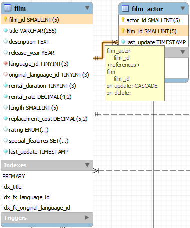
Mousing over a relationship connector highlights the connector and the related keys as shown in the following figure. The film and the film_actor tables are related on the film_id field and these fields are highlighted in both tables. Since the film_id field is part of the primary key in the film_actor table, a solid line is used for the connector between the two tables. After mousing over a relationship for a second, a yellow box is displayed that provides additional information.
Figure 9.11 The Relationship Connector
If the placement of a connection’s caption is not suitable, you can change its position by dragging it to a different location. If you have set a secondary caption, its position can also be changed. For more information about secondary captions, see Section 9.1.4.3, “Connection Properties”. Where the notation style permits, Classic for example, the cardinality indicators can also be repositioned.
The relationship notation style in Figure 9.11, “The Relationship Connector” is the default, crow’s foot. You can change this if you are using a commercial version of MySQL Workbench. For more information, see Section 9.1.1.1.5.4, “The Relationship Notation Submenu”.
You can select multiple connections by holding down the Control key as you click a connection. This can be useful for highlighting specific relationships on an EER diagram.
9.1.4.2 The Relationship Editor
Double-clicking a relationship on the EER diagram canvas opens the relationship editor. This has two tabs: Relationship, and Foreign Key.
The Relationship Tab
In the Relationship tab, you can set the caption of a relationship using the Caption field. This name displays on the canvas and is also the name used for the constraint itself. The default value for this name is fk_source_table_destination_table. Use the Model menu, Menu Options menu item to set a project-specific default name for foreign keys. To change the global default, see Section 3.2.4, “Modeling Preferences”.
You can also add a secondary caption and a caption to a relationship.
The Visibility Settings section is used to determine how the relationship is displayed on the EER Diagram canvas. Fully Visible is the default but you can also choose to hide relationship lines or to use split lines. The split line style is pictured in the following figure.
Figure 9.12 The Split Connector
Note
A broken line connector indicates a nonidentifying relationship. The split line style can be used with either an identifying relationship or a nonidentifying relationship. It is used for display purposes only and does not indicate anything about the nature of a relationship.
To set the notation of a relationship use the Model menu, Relationship Notation menu item. For more information, see Section 9.1.1.1.5.4, “The Relationship Notation Submenu”.
The Foreign Key Tab
The Foreign Key tab contains several sections: Referencing Table, Cardinality and Referenced Table.
The Mandatory check boxes are used to select whether the referencing table and the referenced table are mandatory. By default, both of these constraints are true (indicated by the check boxes being checked).
The Cardinality section has a set of radio buttons that enable you to choose whether the relationship is one-to-one or one-to-many. There is also a check box that enables you to specify whether the relationship is an identifying relationship.
9.1.4.3 Connection Properties
Right-click a connection to select it. When a connection is selected, it is highlighted and its properties are displayed in the properties palette. Connection properties are different from the properties of other objects. The following list describes them:
caption: The name of the connection. By default, the name is the name of the foreign key and the property is centered above the connection line.captionXOffs: The X offset of the caption.captionYOffs: The Y offset of the caption.comment: The comment associated with the relationship.drawSplit: Whether to show the relationship as a continuous line.endCaptionXOffs: The X termination point of the caption offset.endCaptionYOffs: The Y termination point of the caption offset.extraCaption: A secondary caption. By default, this extra caption is centered beneath the connection line.extraCaptionXOffs: The X offset of the secondary caption.extraCaptionYOffs: The Y offset of the secondary caption.mandatory: Whether the entities are mandatory. For more information, see Section 9.1.4.2, “The Relationship Editor”.many: False if the relationship is a one-to-one relationship.middleSegmentOffset: The offset of the middle section of the connector.modelOnly: Set when the connection will not be propagated to the DDL. It is just a logical connection drawn on a diagram. This is used, for example, when drawingMyISAMtables with a visual relationship, but with no foreign keys.name: The name used to identify the connection on the EER Diagram canvas. Note that this is not the name of the foreign key.referredMandatory: Whether the referred entity is mandatory.startCaptionXOffs: The start of the X offset of the caption.startCaptionYOffs: The start of the Y offset of the caption.
In most cases, you can change the properties of a relationship using the relationship editor rather than the Properties palette.
If you make a relationship invisible by hiding it using the relationship editor’s Visibility Settings, and then close the relationship editor, you will no longer be able to select the relationship to bring up its relationship editor. To make the relationship visible again, you must expand the table object relating to the relationship in the Layers palette and select the relationship object. To edit the selected object, right-click it, then select Edit Object. You can then set the Visibility Settings to Fully Visible. The relationship will then be visible in the EER Diagram window.
9.1.5 Creating Views
You can add views to a database either from the Physical Schemata section of the MySQL Model page or from the EER Diagram.
9.1.5.1 Adding Views to the Physical Schemata
To add a view, double-clicking the Add View icon in the Physical Schemata section of the MySQL Model page. The default name of the view is view1. If a view with this name already exists, the new view is named view2.
Adding a new view automatically opens the view editor docked at the bottom of the application. For information about using the view editor, see Section 9.1.5.3, “The View Editor”.
Right-clicking a view opens a pop-up menu with the following items:
Cut ‘
view_name’The ‘
view_name’ is only cut from the EER canvas, and not removed from the schema.Copy ‘
view_name’Paste
Edit View…
Edit in New Window…
Copy SQL to Clipboard
Delete ‘
view_name’: deletes from both the EER canvas and schema.Remove ‘
view_name’: deletes from the EER canvas, but not the schema.
If the table editor is not open, the Edit View… item opens it. If it is already open, the selected table replaces the previous one. Edit in New Window… opens a new view editor tab.
The cut and copy items are useful for copying views between different schemata. Copy SQL to Clipboard copies the CREATE VIEW statement to the clipboard.
Warning
Use the Delete ‘view_name’ item to remove a view from the database. There will be no confirmation dialog box.
Any views added to the Physical Schemata section also show up in the Catalog palette on the left side of the application. They may be added to an EER Diagram, when in the EER Diagram tab, by dragging and dropping them from this palette.
9.1.5.2 Adding Views to an EER Diagram
Views can also be added to an EER Diagram using the View tool on the vertical toolbar. Make sure that the EER Diagram tab is selected, then left-click the view icon on the vertical toolbar. The view icon is the two overlapping rectangles found below the table icon.
Clicking this icon changes the mouse pointer to a view pointer. To change the mouse pointer to a view pointer from the keyboard, use the V key.
Choosing the View tool changes the contents of the toolbar that appears immediately below the main menu bar. When the Views pointer is active, this toolbar contains a schemata list and a color chart list. Use these lists to select the appropriate schema and color accent for the new view. Make sure that you associate the new view with a database. The color of your view can be changed using the Properties palette.
Create a view by clicking anywhere on the EER Diagram canvas. This creates a new view with the default name view1. To revert to the default mouse pointer, click the arrow icon at the top of the vertical toolbar.
Right-clicking a view opens a pop-up menu. With the exception of the delete item, these menu items function as described in Section 9.1.5.1, “Adding Views to the Physical Schemata”. The behavior of the delete option is determined by your MySQL Workbench options settings. For more information, see Section 3.2.4, “Modeling Preferences”.
9.1.5.3 The View Editor
To invoke the view editor, double-click a view object on the EER Diagram canvas or double-click a view in the Physical Schemata section on the MySQL Model page. This opens the view editor docked at the bottom of the application. Double-clicking the title bar undocks the editor. Do the same to redock it. Any number of views may be open at the same time. Each additional view appears as a tab at the top of the view editor.
There are three tabs at the bottom of the view editor: View, Comments, and Privileges. Navigate between different tabs using the mouse or from the keyboard by pressing Control+Alt+Tab.
The View Tab
Use the View tab to perform the following tasks:
Rename the view using the Name text box.
Enter the SQL to create a view using the SQL field.
Comment a view using the Comments text area.
The Comments Tab
This tab enables you to enter comments for a particular view.
The Privileges Tab
The Privileges tab of the view editor functions in exactly the same way as the Privileges tab of the routine editor. For more information, see Section 9.1.6.1.2.2, “The Privileges Tab”.
9.1.5.4 Modifying a View Using the Properties Palette
When you select a view on the EER Diagram canvas, its properties are displayed in the Properties palette. Most of the properties accessible from the Properties palette apply to the appearance of a view on the EER Diagram canvas.
For a list of properties accessible through the Properties palette, see Section 9.1.1.12, “The Properties Palette”.
9.1.6 Creating Routines and Routine Groups
You can add Routine Groups to a database either from the Physical Schemata section of the MySQL Model page or from an EER Diagram. Routines may be added only from the Physical Schemata section of the MySQL Model page.
To view an existing schema, along with its Routines and Routine Groups, choose Database, Reverse Engineer… from the main menu. After the schema has been added to the current model, you can see the schema objects on the Physical Schemata panel on the MySQL Model page. The Routines and Routine Groups are listed there.
MySQL Workbench unifies both stored procedures and stored functions into one logical object called a Routine. Routine Groups are used to group related routines. Define Routine with the Routine Group Editor to assign specific routines to a group, using a drag and drop interface.
When designing an EER Diagram, you can place the Routine Groups on the canvas by dragging them from the Catalog Palette. Placing individual routines on the diagram is not permitted, as it would clutter the canvas.
9.1.6.1 Routines
9.1.6.1.1 Adding Routines to the Physical Schemata
To add a routine, double-click the Add Routine icon in the Physical Schemata section of the MySQL Model page. The default name of the routine is routine1. If a routine with this name already exists, the new routine is named routine2.
Adding a new routine automatically opens the routine editor docked at the bottom of the application. For information about using the routine editor, see Section 9.1.6.1.2, “The Routine Editor”.
Right-clicking a routine opens a pop-up menu with the following items:
Rename
Cut ‘
routine_name’Copy ‘
routine_name’Paste
Edit Routine…
Edit in New Window…
Copy SQL to Clipboard
Delete ‘
routine_name’
The Edit Routine… item opens the routine editor.
The cut and paste items are useful for copying routines between different schemata.
Note
Deleting the code for a routine from the Routines tab of the Routine Group Editor results in removal of the routine object from the model.
Note
To remove a routine from a routine group, use the controls on the Routine Group tab of the Routine Group Editor.
The action of the delete option varies depending upon how you have configured MySQL Workbench. For more information, see Section 3.2.4, “Modeling Preferences”.
9.1.6.1.2 The Routine Editor
To invoke the routine editor, double-click a routine in the Physical Schemata section on the MySQL Model page. This opens the routine editor docked at the bottom of the application. Any number of routines may be open at the same time. Each additional routine appears as a tab at the top of the routine editor.
Routine and Privileges tabs appear at the bottom of the routine editor. Navigate between different tabs using the mouse or from the keyboard by pressing Control+Alt+Tab.
9.1.6.1.2.1 The Routine Tab
Use the Routine tab of the routine editor to perform the following tasks:
Rename the routine using the Name field.
Enter the SQL to create a routine using the SQL field.
9.1.6.1.2.2 The Privileges Tab
The Privileges tab of the routine editor allows you to assign specific roles and privileges. You may also assign privileges to a role using the role editor. For a discussion of this topic, see Section 9.1.1.5.1, “Adding Roles”.
When this tab is first opened, all roles that have been created are displayed in the list on the right. Move the roles you wish to associate with this table to the Roles list on the left. Do this by selecting a role and then clicking the < button. Use the Shift key to select multiple contiguous roles and the Control key to select noncontiguous roles.
To assign privileges to a role, click the role in the Roles list. This displays all available privileges in the Assigned Privileges list. The privileges that display are:
ALLCREATEDROPGRANT OPTIONREFERENCESALTERDELETEINDEXINSERTSELECTUPDATETRIGGER
You can choose to assign all privileges to a specific role or any other privilege as listed previously. Privileges irrelevant to a specific table, such as the FILE privilege, are not shown.
If a role has already been granted privileges on a specific table, those privileges show as already checked in the Assigned Privileges list.
9.1.6.2 Routine Groups
9.1.6.2.1 Adding Routine Groups to the Physical Schemata
Double-clicking the Add Routine Group icon in the Physical Schemata section of the MySQL Model page adds a routine group with the default name of routines1. If a routine group with this name already exists, the new routine group is named routines2.
Adding a new routine group automatically opens the routine groups editor docked at the bottom of the application. For information about using the routine groups editor, see Section 9.1.6.2.3, “The Routine Group Editor”.
Right-clicking a routine group opens a pop-up menu with the following items:
Rename
Cut ‘
routine_group_name’Copy ‘
routine_group_name’Edit Routine…
Edit in New Window…
Copy SQL to Clipboard
Delete ‘
routine_group_name’
The Edit Routine Group… item opens the routine group editor, which is described in Section 9.1.6.2.3, “The Routine Group Editor”.
The cut and paste items are useful for copying routine groups between different schemata.
Deleting a routine group from the MySQL Model page removes the group but does not remove any routines contained in that group.
Any routine groups added to the Physical Schemata also show up in the Catalog palette on the right side of the application. They may be added to an EER diagram by dragging and dropping them from this palette.
9.1.6.2.2 Adding Routine Groups to an EER Diagram
To add routine groups to an EER Diagram, use the Routine Groups tool on the vertical toolbar. Make sure that the EER Diagram tab is selected, then right-click the routine groups icon on the vertical toolbar. The routine groups icon is immediately above the lowest toolbar separator.
Clicking the mouse on this icon changes the mouse pointer to a routine group pointer. You can also change the mouse pointer to a routine pointer by pressing the G key.
Choosing the Routine Group tool changes the contents of the toolbar that appears immediately below the menu bar. When the Routine Groups pointer is active, this toolbar contains a schemata list and a color chart list. Use these lists to select the appropriate schema and color accent for the new routine group. Make sure that you associate the new routine group with a database. The color of your routine group can be changed later using the Properties palette.
Create a routine group by clicking anywhere on the EER Diagram canvas. This creates a new routine group with the default name routines1. To revert to the default mouse pointer, click the arrow icon at the top of the vertical toolbar.
Right-clicking a routine group opens a pop-up menu. With the exception of the delete option and rename options, these menu options function as described in Section 9.1.6.2.1, “Adding Routine Groups to the Physical Schemata”. There is no rename option, and the behavior of the delete option is determined by your MySQL Workbench options settings. For more information, see Section 3.2.4, “Modeling Preferences”.
9.1.6.2.3 The Routine Group Editor
To invoke the routine group editor, double-click a routine group object on the EER Diagram canvas or double-click a routine group in the Physical Schemata section on the MySQL Model page. This opens the routine group editor docked at the bottom of the application. Double-clicking the title bar undocks the editor. Do the same to redock it. Any number of routine groups may be open at the same time. Each additional routine group appears as a tab at the top of the routine editor,
Routine group and Privileges tabs appear at the bottom of the routine editor. Navigate between different tabs using the mouse or from the keyboard by pressing Control+Alt+Tab.
9.1.6.2.3.1 The Routine Groups Tab
Use the Routine Groups tab of the routine groups editor to perform the following tasks:
Rename the routine group using the Name field.
Add routines to the group by dragging and dropping them.
Add comments to the routine group.
9.1.6.2.3.2 The Privileges Tab
The Privileges tab of the routine group editor functions in exactly the same way as the Privileges tab of the table editor. For more information, see Section 9.1.6.1.2.2, “The Privileges Tab”.
9.1.6.2.3.3 Modifying a Routine Group Using the Properties Palette
When you select a routine group on the EER Diagram canvas, its properties are displayed in the Properties palette. All of the properties accessible from the Properties palette apply to the appearance of a routine group on the EER Diagram canvas.
For a list of properties accessible through the Properties palette, see Section 9.1.1.12, “The Properties Palette”.
9.1.7 Creating Layers
You can add layers to a database only from an EER Diagram. Layers are used to help organize objects on the canvas. Typically, related objects are added to the same layer; for example, you may choose to add all your views to one layer.
9.1.7.1 Adding Layers to an EER Diagram
To add layers to an EER Diagram, use the Layer tool on the vertical toolbar. Select an EER Diagram tab and left-click the layer icon on the vertical toolbar. The layer icon is the rectangle with an ‘L’ in the lower left corner and it is found below the eraser icon.
Clicking the mouse on this icon changes the mouse pointer to a layer pointer. You can also change the mouse pointer to a layer pointer by pressing the L key.
Choosing the Layer tool changes the contents of the toolbar that appears immediately below the menu bar. When the Layers pointer is active, this toolbar contains a color chart list. Use this list to select the color accent for the new layer. The color of your layer can be changed later using the Properties palette.
Create a layer by clicking anywhere on the EER Diagram canvas and, while holding the left mouse button down, draw a rectangle of a suitable size. This creates a new layer with the default name layer1. To revert to the default mouse pointer, click the arrow icon at the top of the vertical toolbar.
The following image shows a layer named “My Sakila Views” with several views:
Figure 9.13 The Layer Object
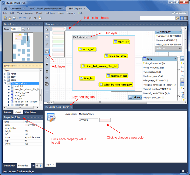
To open the layer editor, either double-click the layer or right-click the layer and choose the edit option. The available context-menu options are:
Cut ‘
layer_name’Copy ‘
layer_name’Paste ‘
a_table_name’Edit ‘
layer_name’Delete ‘
layer_name’
Note
A layer may also be edited via Properties Editor on the left panel, and it offers additional edit options.
The cut and copy items are useful for copying layers between different schemata.
Since layers are not schema objects, no confirmation dialog box opens when you delete a layer regardless of how you have configured MySQL Workbench. Deleting a layer does not delete schema objects from the catalog.
9.1.7.1.1 Adding Objects to a Layer
To add an object to a layer, drag and drop it directly from the Catalog palette onto a layer. If you pick up an object from an EER diagram, you must press Control as you drag it onto the layer, otherwise it will not be “locked” inside the layer.
Locking objects to a layer prevents their accidental removal. You cannot remove them by clicking and dragging; to remove an object, you also must press the Control key while dragging it.
As a visual cue that the object is being “locked”, the outline of the layer is highlighted as the object is dragged over it.
If you drag a layer over a table object, the table object will automatically be added to the layer. This also works for multiple table objects.
Layers cannot be nested. That is, a layer cannot contain another layer object.
9.1.7.2 Modifying a Layer Using the Properties Palette
Choosing “Edit” allows you to edit the layer name and layer background color, and the “Properties Editor” offers additional edit options.
When you select a layer on the EER Diagram canvas, its properties are displayed in the Properties palette. The properties accessible from the Properties palette apply to the appearance of a layer on the EER Diagram canvas.
In some circumstances, you may want to make a layer invisible. Select the layer and, in the Properties palette, set the visible property to False. To locate an invisible object, open the Layers palette and select the object by double-clicking it. After an object is selected, you can reset the visible property from the Properties palette.
For a list of properties accessible through the Properties palette, see Section 9.1.1.12, “The Properties Palette”. In addition to the properties listed there, a layer also has a description property. Use this property to document the purpose of the layer.
9.1.8 Creating Notes
You can add notes to a database only from the Model Notes section of the MySQL Model page. Notes are typically used to help document the design process.
9.1.8.1 Adding Notes
Double-clicking the Add Note icon in the Model Notes section of the MySQL Model page adds a note with the default name of note1. If a note with this name already exists, the new note is named note2.
Adding a new note automatically opens the note editor docked at the bottom of the application. For information about using the note editor, see Section 9.1.8.2, “The Note Editor”.
Right-clicking a note opens a pop-up menu with the following items:
Rename
Cut ‘
note_name’Copy ‘
note_name’Delete ‘
note_name’
The Edit Note… item opens the note editor. For information about using the note editor, see Section 9.1.8.2, “The Note Editor”.
The cut and copy items are useful for copying notes between different schemata.
Notes can be added only on the MySQL Model page.
9.1.8.2 The Note Editor
To invoke the note editor, double-click a note object in the Model Note section on the MySQL Model page. This opens the note editor docked at the bottom of the application. Double-clicking the note tab undocks the editor. Double-click the title bar to redock it. Any number of notes may be open at the same time. Each additional note appears as a tab at the top of the note editor.
Use the editor to change the name of a note or its contents.
9.1.9 Creating Text Objects
Text objects are applicable only to an EER diagram. They can be used for documentation purposes; for example, to explain a grouping of schema objects. They are also useful for creating titles for an EER diagram should you decide to export a diagram as a PDF or PNG file.
9.1.9.1 Adding Text Objects to an EER Diagram
To add text objects to an EER Diagram, use the Text Object tool on the vertical toolbar. Make sure that the EER Diagram tab is selected, then right-click the text object icon on the vertical toolbar. The text object icon is the rectangular icon found below the label icon.
Clicking the mouse on this icon changes the mouse pointer to a text object pointer. You can also change the mouse pointer to a text object pointer by pressing the N key.
Choosing the Text Object tool changes the contents of the toolbar that appears immediately below the menu bar. When the Text Object pointer is active, this toolbar contains a color chart list. Use this list to select the color accent for the new text object. The color of your text object can be changed later using the Properties palette.
Create a text object by clicking anywhere on the EER Diagram canvas. This creates a new text object with the default name text1. To revert to the default mouse pointer, click the arrow icon at the top of the vertical toolbar.
Right-clicking a text object opens a pop-up menu. These menu options are identical to the options for other objects. However, since a text object is not a database object, there is no confirmation dialog box when you delete a text object.
9.1.9.2 The Text Object Editor
To invoke the text object editor, double-click a text object on the EER Diagram canvas. This opens the editor docked at the bottom of the application. Double-clicking the text object table undocks the editor. Double-click the title bar to redock it. Any number of text objects may be open at the same time. Each additional text objects appears as a tab at the top of the text editor.
Use the editor to change the name of a text object or its contents.
9.1.9.2.1 Modifying a Text Object Using the Properties Palette
When you select a text object on the EER Diagram canvas, its properties are displayed in the Properties palette. Most of the properties accessible from the Properties palette apply to the appearance of a view on the EER Diagram canvas.
For a list of properties accessible through the Properties palette, see Section 9.1.1.12, “The Properties Palette”.
There is no property in the Properties palette for changing the font used by a text object. To do so, choose the Appearance tab of the Workbench Preferences dialog. For more information, see Preferences: Modeling: Appearance.
9.1.10 Creating Images
Images exist only on the EER Diagram canvas; you can add them only from the EER Diagram window.
9.1.10.1 Adding Images to an EER Diagram
To add images to an EER Diagram, use the Image tool on the vertical toolbar. Make sure that the EER Diagram tab is selected, then right-click the image icon on the vertical toolbar. The image icon is the icon just above the table icon.
Clicking the mouse on this icon changes the mouse pointer to an image pointer. You can also change the mouse pointer to an image pointer by pressing the I key.
Create an image by clicking anywhere on the EER Diagram canvas. This opens a file open dialog box. Select the desired image, then close the dialog box to create an image on the canvas. To revert to the default mouse pointer, click the arrow icon at the top of the vertical toolbar.
Right-clicking this object opens a pop-up menu with the following items:
Cut
'Image'Copy
'Image'Edit Image…
Edit in New Window…
Delete
'Image'
These menu items function in exactly the same way as they do for other objects on an EER diagram. However, images are not database objects so there is no confirmation dialog box when they are deleted.
9.1.10.2 The Image Editor
To invoke the image editor, double-click an image object on an EER Diagram canvas. This opens the image editor docked at the bottom of the application. Double-clicking the image editor tab undocks the editor. Double-click the title bar to redock it. Any number of images may be open at the same time. Each additional image appears as a tab at the top of the image editor.
9.1.10.2.1 The Image Tab
Use the Image tab of the image editor to perform the following tasks:
Rename the image using the Name text box.
Browse for an image using the Browse button.